Benutzer-Werkzeuge
Inhaltsverzeichnis
Controller Hardware
Arduino Hardware
Based on the first tests, which are described here, I have created a circuit board.
The printed circuit board can be assembled in two assembly variants. The easier to assemble variant „Shield“ is intended as an add-on for an Arduino Uno R3 SMD. Precondition is that the port A6, which is only available in the SMD version of the ATMega328, is also accessible via the PCB. This is not the case for all versions. All other connections are needed for the encoders and the peripherals. The two pulse outputs of the encoders are connected to ports of the Arduino. The push buttons are connected to an I²C port expander PCF8574. The interrupt output initiates port polling via A6 of the Arduino when the state changes.
In addition to this hardware
- and the six rotary encoders
are required.
Printed circuit board (PCB)
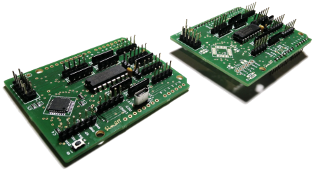
The printed circuit board is designed in the Arduino UNO shield format. It contains an Arduino Pro Mini (ATMega328) when fully assembled and can then be used separately. The downgraded version (Shield) is plugged onto an Arduino Uno R3 SMD. Then the Ethernet module and the 6 rotary encoders are connected. Two single buttons can be connected.

Variant Encoder Shield
The Encoder-Shield variant is only equipped with THT components, so that the construction is quite simple.
The pin headers on the backside are used to connect to the Arduino Uno R3, which is also the power supply. J-A6 must be connected separately to A6 of the Arduino. The encoders are connected to the connectors J-ENC1 to J-ENC6 and the Ethernet module to J1.
Variant Encoder Controller
The Encoder Controller variant contains the THT components of the Encoder Shield variant as well as the components of an Arduino Pro Mini. The pin headers on the bottom and J-A6 are not required. Power can be supplied via a micro-USB socket, but it is also possible to use the programming connector FTDI. The encoders are connected to the connectors J-ENC1 to J-ENC6 and the Ethernet module is connected to J1.
- Printed circuit board ARDU-ENC in Arduino-Uno format with controller assembly
- Ethernet module WizNET W5500 at connector J3, see here
- Rotary encoder with push button (same number of pulses as detents), see here
To build this variant it is necessary to program a bootloader in the ATMega328 so that the IDE can upload the sketches and the ATMega can start them. This can be done with an Arduino Uno. Basic hints for initial programming can be found here:
I have described the concrete procedure here (german).
For sketch programming, a USB-to-serial converter is then required at the FTDI port, as shown
here.
Pin assignment
J2 - Power connector
The module can be supplied with power via USB.
J-ENC1 to J-ENC6 (Rotary encoder)
Five-pole connectors are provided for the 6 rotary pulse generators of the controller.
1  2  3  4  5
o  o  o  o  o
|  |  |  |  |
|  |  |  Ground for Push Button and Encoder
|  |  c.w. Following Signal
|  Push Button
c.w. Leading Signal

Possible Encoder wiring
As encoder types with 11mm width can be used.
Here are some examples. They must be encoders with the same number of pulses as detents, e.g. 20 pulses and 20 detents.
There is the possibility of connection via a printed circuit board with/without plug connector or, in case of very narrow installation spaces, directly at the encoder.
The pin assignment on the cable results from the original use of a 16mm rotary pulse encoder and is based on a number of the pinout of the 10-pin connector on ITRA rotary pulse encoders.
Example 11mm-Encoder Alpha RE111F-41B3N-20F-20P (Top view)
A   o -------------  (3) c.w. Following Signal
PB            o ---  (4) Ground for Push Button
C   o -------------  (5) Ground for Encoder
PB            o ---  (2) Push Button
B   o -------------  (1) c.w. Leading Signal
If the direction of rotation is reversed, then it helps to swap the A and B connections.
J1 - Ethernet

The Ethernet module is connected via SPI, the assigned Arduino ports are D10 … D13. Additional information you find hier (german).
     10   9
      o   o 5P
MISO  o   o GND
MOSI  o   o RES
CS    o   o
SCK   o   o
      2   1
This connector is also used for initial programming the bootloader to the ATmega328.
Connector FTDI

This connector allows the controller to be connected to a USB-to-serial adapter and then programmed. The pinout corresponds to the pinout of an Arduino Pro Mini. Rx, TX are for data transmission, the DTR signal controls the reset of the Pro Mini. There are versions with a FTDI chip or also with a CH340G chip.
1  2  3  4  5  6
o  o  o  o  o  o
|  |  |  |  |  |
|  |  |  |  Vss (GND)
|  |  |  Vcc (5P)
|  |  Rx (Input at ATMega)
|  Tx (Output at ATMega)
DTR (for Reset)
Extensions
Port Extension for Switches
The port extension is only suitable for the controller version.
For the query of switch events, a circuit board was created which has the same size as the Arduino UNO, but there are no connectors of an Arduino Shield. A 5-pin connector is provided for connection to the encoder-controller board.

The figure shows the complete assembly of the controller with the port extension and the Ethernet module. With this extension it is possible to emulate switches of the panel of a small aircraft. This includes starter, light switch, fuel pump, tank, flaps, gear.
Further information can be found in the section Extensions.
Application Example


Software
Arduino Sketch
The encoder controller is designed to connect to and transmit events to PC software.
The Ethernet module is connected to the network and requires a network address assigned via DHCP. The UDP protocol is used for the data connection. Please note that a unique MAC address and a unique port is always assigned. Both are defined in the sketch.
After the connection is established, key and encoder events can be sent to the PC software.
Communication software
The communication software establishes the connection between the Flight Simulator and the Encoder Controller. If a PC has more than one network card, then the configuration file of the client/plugin must be used to define this card. At startup the found network adapters are listed with their ID.
Via the network adapter, a request is sent to the broadcast address of the network segment and the UDP port assigned to the respective panel function (this must match the sketch) to search for the Encoder Controller. The Encoder Controller receives this request and thus knows the IP address of the sending communication software. The confirmation is then sent to this IP address, whereby the controller IP address is transmitted to the communication software. The connection is now established. The controller now knows the IP address of the Flight Simulator and the Flight Simulator knows the IP address of the controller.
Now events of the encoders can be sent via UDP to the client/plugin, which converts them into flight simulator events.
Cyclically it is queried whether the controller is still in the system. If no response is received to this request within a certain period of time, the client/plugin returns to the connection establishment phase and sends again search requests on the broadcast address.
SimConnect Client
 The SimConnect client (FSX, FS2020, P3D) is a stand-alone program and can be called directly from a folder, e.g. the installation folder. The configuration file can be created in this folder or in a subfolder of the AppData area.
.\AppData\Roaming\Sim&IT\SimConnect\Encoder-Control.cfg
→ Further information about the SimConnect client and its configuration can be found here
X-Plane Plugin
 The X-Plane plugin corresponds to a DLL. These are stored in the subfolder
 .\ressources\plugins. The found plugin can be displayed in the started flight simulator via the menu. In the info area either the connection to the encoder controller or the selection of network adapters is displayed if more than one adapter was found. This adapter must be defined in the configuration file.
.\AppData\Roaming\Sim&IT\X-Plane-Plugins\Encoder-Control.cfg
→ Further information about the X-Plane plugin and its configuration can be found here.
Functions
The encoder controller realizes the following functions unless other settings are set via the configuration variables.
Encoder1
The encoder sets the OBS1. A short press on the encoder axis switches to a quick adjustment mode (+/- 5°) and back. After a few seconds without any input, it will return to normal mode.
Encoder2
The encoder sets the OBS2. A short press on the encoder axis switches to a quick adjustment mode (+/- 5°) and back. After a few seconds without any input, it will return to normal mode.
Encoder3
The encoder sets the ADF course. A short press on the encoder axis switches to a quick adjustment mode (+/- 5°) and back. After a few seconds without any input, it will return to normal mode.
Encoder4
The encoder sets the Haeding Bug. A short press on the encoder axis switches to a quick adjustment mode (+/- 5°) and back. After a few seconds without any input, it will return to normal mode.
Encoder5
The encoder sets the barometric pressure (QNH). A short pressure on the encoder axis sets to 29.92inHg or 1013.2hPa (STD).
Encoder6
A short press on the encoder axis activates the encoder. The encoder sets the gyro. A long press synchronizes the gyro with the magnetic compass.
For other applications the functions can be changed via configuration variables. This is described in the section on the communication software.
Links
Installation instructions:
Development Encoder Shields (german)
Programming the bootloader (german)
Building a cockpit panel PC (german)
Seiten-Werkzeuge
