Benutzer-Werkzeuge
Inhaltsverzeichnis
Extensions
Port Extension for Switches
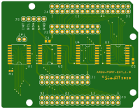
For the query of switch events, a circuit board was created as add on to the Encoder Controller which has the same size as the Arduino UNO, but there are no connectors of an Arduino Shield. A 5-pin connector is provided for connection to the encoder-controller board. The connection contains the power supply +5P and GND and the I²C signals SDA, SCL and INT.
On the controller board R1 must be equipped to connect the 5V on the connector next to the GND line.
Printed circuit board
Schematic
Assembly
Bill of Material
The switches must be connected to ground when closed. With this assembly it is possible to reproduce the switches from the panel of a small airplane. This includes:
- Master Battery
- Alternator 1/2
- Starter 1/2
- Fuelpump 1/2
- Prop Sync
- Avionics Master
- Lights
- Tank Selector
- Flaps
- Gear
- Parking Brake
- Pitot Heat
- Carburator Heat
 The figure shows the complete assembly of the controller with the port extension and the Ethernet module. Since the controller and the port expansion are in Arduino format, both boards could be mounted on top of each other with the appropriate distance if necessary.
 The display is an OLED display with a resolution of 128×32 pixels, which was connected via 4 lines as an I²C device. The display controller is a SSD1306. Because of the small size of the Arduino's memory a very simple library was integrated. This library is named ss_oled in the Arduino IDE.
The display is used to show information during programming. This is not necessary in normal operation.
Pin assignment
J5 Connection to the Controller
o  o  o  o  o
|  |  |  |  |
|  |  |  |  GND (VSS)
|  |  |  5P (VDD) at Encoder-Controller R1 (0 Ohm) must assembled
|  |  SDA (I²C-Data of ATMega)
|  SCL (I²C-Clock of ATMega)
INT (I²C-Interrupt at ATMega A6)
The controller sketch detects a connected port extension, in the client program all switches are disabled by default, otherwise all switch functions would be interpreted as „OFF“. These must be enabled via the configuration file. Some functions are additionally configurable. These functions are described in the communication software section.
With the communication software of the SimConnect Client and the X-Plane Plugin, the following switching functions are supported with switches at J1 and J2. A 20-pin ribbon cable with a post connector is connected here. All common GND poles of the switches are connected together on the panel and connected to pin1/2 of the ribbon cable. The other lines are separated on the panel and connected to the switch pole of the switch.
J1 - Switches 1
                 1   2
GND              o   o GND
Panel Light      o   o Pitot Heat
Strobe/BCN Light o   o Nav Light
Taxi Light       o   o Landing Light
Carburator Heat  o   o Fuelpump1
Avionics         o   o Starter1 - LEFT
Starter1 - RIGHT o   o Starter1 - START
Starter1 - BOTH  o   o Starter1-OFF
Generator1       o   o Batteriehauptschalter
5P               o   o 5P
                19   20
J2 - Switches 2
                 1   2
GND              o   o GND
Flaps Full Down  o   o Flaps Pos2
Flaps Pos1       o   o Gear
Parking Brake    o   o Fuel Tank OFF
Tanksel R (L->R) o   o Tankselector L (R->L)
Propeller Sync   o   o Starter2 - LEFT
Starter2 - RIGHT o   o Starter2 - START
Starter2 - BOTH  o   o Starter2 - OFF
Generator2       o   o Fuelpump2
5P               o   o 5P
                19   20
J3 and J4 - Switches
If each individual switch is to be connected separately, so every switch with two potential-free wires, then the 32-pole connectors J3 and J4 can also be used. In this case, the assignment applies:
- alle geradzahligen Pins führen GND-Potential
- die ungeradzahligen Pins sind die Schaltkontakte
- J1/2 Pin3 führt auf J3/J4 Pin1
- J1/2 Pin4 führt auf J3/J4 Pin3
- …
- J1/J2 Pin18 führt auf J3/J4 Pin31
With reference to the port expander (see schematic):
- J3 odd Pins 01 … 15 ⇒ Port expander U2 Port P7 … P0
- J3 odd Pins 17 … 31 ⇒ Port expander U1 Port P7 … P0
- J4 odd Pins 01 … 15 ⇒ Port expander U4 Port P7 … P0
- J4 odd Pins 17 … 31 ⇒ Port expander U3 Port P7 … P0
Switch Configuration
The configuration file of the communication software has a section [SWITCHES]. The variables have the following meaning:
General:
0 - Switch deactivated
1 - Switch active
Number of engines:
2 - STARTER, FUELPUMP, MASTERALT if 2 switches are present on a two 2-engined aircraft. If a 1 is entered in this position for a 2-engined aircraft, the switch of the first machine acts for both machines.
With the starter variant, a distinction must be made between propeller and turbine propulsion. This is done in a section [AIRCRAFT] in the configuration file with the variable TYPE with the value 0 or 1.
| Aircraft Type | StarterX-OFF | StarterX-RIGHT | StarterX-LEFT | StarterX-BOTH | StarterX-START |
|---|---|---|---|---|---|
| (0) Propeller | Ignition off | Right ignition circuit | Left ignition circuit | Both ignition circuits | Start |
| (1) Turbine | Turbine stop | — | — | Turbine on | Start |
Flaps: For the variable FLAPS there are the following values possible:
0 - no flap lever
1 - four positions with 3 signals, all signals open = UP
2 - three positions with 3 signals e.g. at rotary switch
3 - three positions with toggle switch, center = open = approach
Three signals are provided for flap control: Position1, Position2, Full Down. Depending on the configuration file, you can implement flaps control with 3 or 4 steps.
| Signal | Open | Pos1 | Pos2 | Full Down |
|---|---|---|---|---|
| (1) Rotary switch 4 positions | Full Up | Pos1 | Pos2 | Full Down |
| (2) Rotary switch 3 positions | —- | Full Up | Middle | Full Down |
| (3) Toggle switch mit center position | Middle | Full Up | —- | Full Down |
There are 2 configuration variables for tank switchover/switch-off, FUELTANKOFF and FUELTANKSEL.
With the signal at Fuel Tank OFF the fuel supply can be switched off.
The tank selection is done with signals Tank Sel L and Tank Sel R.
- Single Prop Engine
(1) - Tank left, Tank right, centre position - both Tanks
- Twinprop Engine with Cross-Feed:
- MS-FS / Prepar3D:
(2) - X-Feed: right to left, left to right, centre position - crossfeed off
- X-Plane:
(2) - X-Feed: right to left, left to right, centre position - crossfeed off(3) - X-Feed: center position - crossfeed off and all tanks selected(4) - Fuel-Transfer From - To
The following variables are defined in the [SWITCHES] section of the configuration file:
AVIONICSMASTER=0  -> {0,1}
CARBHEAT=0        -> {0,1}
FLAPS=0           -> {0,1,2,3}
FUELPUMP=0        -> {0,1,2}
FUELVALVE=0       -> {0,1,2}  alternative to FUELPUMP
FUELTANKOFF=0     -> {0,1}
FUELTANKSEL=0     -> {0,1,2,3,4}
GEAR=0            -> {0,1}
LANDINGLIGHT=0    -> {0,1}
MASTERALT=0       -> {0,1,2}
MASTERBAT=0       -> {0,1}
NAVLIGHT=0        -> {0,1}
PANELLIGHT=0      -> {0,1}
PARKINGBRAKE=0    -> {0,1}
PITOTHEAT=0       -> {0,1}
PROPSYNC=0        -> {0,1}
STARTER=0         -> {0,1,2}
STROBELIGHT=0     -> {0,1}
TAXILIGHT=0       -> {0,1}
Seiten-Werkzeuge
