Benutzer-Werkzeuge
Inhaltsverzeichnis
X-Plane Plugin
System description
The plugin only supports the Windows version of X-Plane.
The X-Plane Plugin SDK2 and X-Plane SDK3 provide access to commands and data references. Plugins allow to send commands to the flight simulator X-Plane with external hardware and to set variables.
The X-Plane plugin communicates directly with the Arduino hardware via the UDP network protocol.
System requirements
To use the X-Plane plugins, an X-Plane version higher than 10.0 is required. A configured network with automatic address assignment (DHCP) is required to assign a valid IP address to the Arduino. This is done, for example, via the router that implements the Internet connection.
Location of the X-Plane plugins:
The plugins *.xpl must be manually copied from the installation folder to the X-Plane plugins folder, this \Ressources\plugins folder is located below the X-Plane installation folder.
The location of the configuration files of the X-Plane plugins is:
Win7 ff: C:\Users\username\AppData\Roaming\Sim&IT\X-Plane-Plugins
These folders are hidden by default.
The configuration file can be displayed and edited with the editor (Programs → Accessories), for example. A corresponding link to the configuration file is created in the program folder during installation.
Software Installation
After starting the setup, you can change the destination folder of the installation and the menu folder of the program group. With „Finish“ the client installation is completed.

After installation, you will find the links to the installation folder of the plugins and to the configuration file for changing the configuration variables of the plugins in the program group Sim&IT X-Plane Plugins, which was preferably specified during installation.
Plugin Configuration
After starting X-Plane, you will find a menu item in the Plugins menu with two sub-items for information and for entering license information. The plugin works without a license for about 10 minutes.
The info area displays either the connection to the Arduino panel and the license information.
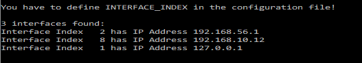
If more than one network adapter was found, they are displayed with the index assigned by the operating system. The index of the network adapter to which the Arduino hardware is connected must be specified in the configuration file
.\AppData\Roaming\Sim&IT\X-Plane-Plugins\Encoder-Control.cfg
with the Configuration Variables INTERFACE_INDEX, to establish a connection.
The program Show NetIndex can also be used to determine the index. This program also shows the installed network adapters and their index in the operating system.
In Windows you can detect the index also with:
wmic path win32_networkadapter get name, index, interfaceindex
Configuration Variables
The configuration variables are followed by a = and then the value to be set.
For all modules there is the section [NET] with the configuration variable
INTERFACE_INDEXfor defining the network adapter if there are several in the system
Configuration of Encoder Controller
For the encoder controller there is the section [ENC1]
ARDU_PORTto define the port of the receiving device if standard port can not be usedRECV_PORTto define the port on the PC, if standard port can not be used
The changed ports must also be defined in the Arduino sketch.
For each encoder (1 to 6) there are configuration settings to define variables or commands in accordance with the files Commands.txt or DataRefs.txt (exemplary for Encoder1):
ROTARY1_CMD_OR_VALUE0 means that commands are defined, 1 means that a variable to be defined is increased or decreased.ROTARY1_VALUEdefines a variable to be changed, prerequisite is the definition ofROTARY1_CMD_OR_VALUE=1ROTARY1_INVERSEchanges the direction of rotation when changing variablesROTARY1_CMD_RIGHTCommand for clockwise directionROTARY1_CMD_LEFTCommand for counterclockwise directionROTARY1_CMD_PBcommand when pressing the encoder axis (Push Button)ROTARY1_CMD_PB_HOLDcommand when pressing the encoder axis for a longer time
There is an additional function for the encoder6. If the option
ROTARY6_PUSH_TO_ACTIVATE
is set to 1, then the encoder is only activated after pressing once.
There are also two individual keys 7 and 8 with the configuration variables (exemplary for key7).
KEY7_CMDcommand when pressing the keyKEY7_CMD_HOLDcommand when pressing the key for a longer time
Tests have shown that calling a command several times during a loop pass has no effect, the command seems to be executed only once, unlike incrementing and decrementing. If there are several identical encoder events in the transmission buffer, changing a variable works better than executing a command.
Configuration of Port Extention for Switches
The configuration of the switches is described in the section Extensions.
Seiten-Werkzeuge
