Inhaltsverzeichnis
Panel Hardware
Arduino Hardware Ethernet
Based on the test setups with the Arduino, decribed here, I developed circuit boards for the avionics panel. The panel dimensions are only 50 x 80 mm. See here the system design.
 The panel is connected to the FS-PC via Ethernet. The Arduino sketch processes the button / encoder events, which are transmitted via UDP (Ethernet) to an interface software on the PC, which generates FS commands from this. The updated variables are transferred to the Arduino panel and displayed there on the LC display. The communication software uses SimConnect clients for MSFS (FSX, FS2020) and P3D as well as X-Plane plug-ins for X-Plane. Further software is not necessary for the operation of the panel.
For the purchase of hardware and the communication software please contact me by e-mail. The hex-files and Arduino sources are also available on request for DIY projects.
For programming the Arduino, a USB-serial adapter such as this one is required.
Variant 1
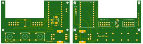
The printed circuit board is equipped with buttons and a rotary encoder. Furthermore, commercially available modules are connected to the printed circuit board. Due to the relatively simple construction and the free availability of the printed circuit board, the module is also suitable for DIY projects. No SMD assembly is used in the preferred assembly of this module.
Two different Ethernet modules can be connected to the PCB. With the ENC28J60, the Arduino must use the IP stack in software, which requires significantly more resources. In addition, the 3.3V regulator is needed for the modules found. The WizNET module W5500 should therefore be preferred.
It is possible to equip an inexpensive rotary encoder with one axis, which is then used to switch between pre- and post-decimal places by pressing the encoder axis. The other possibility is to equip a much more expensive rotary encoder with two shafts. Finding suitable knobs for this is problematic. A source of 3D printing data for a suitable pair of knobs is listed in the parts list.
A separate sketch is used for each of the two variants. The identifier that is sent when the connection is established may then be processed in the client/plugin.
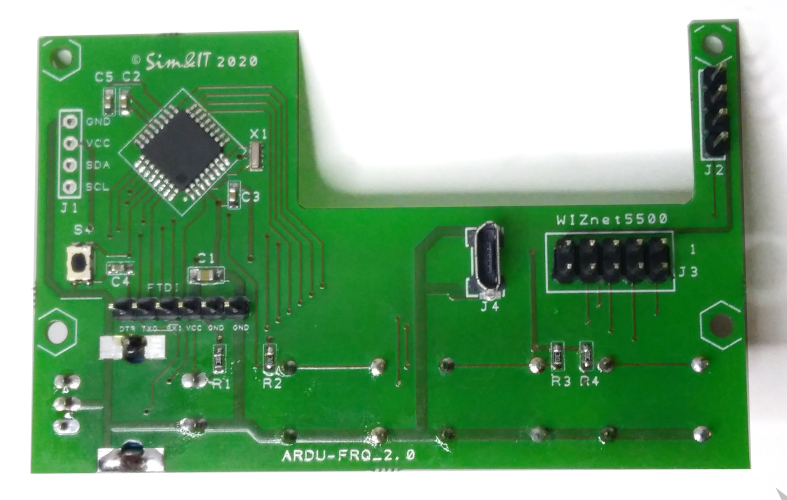
- Printed Circuit Board ARDU-FRQ 5cm x 8cm
- Arduino Pro Mini (5V, 16 MHz) in socket U1, the Pro Mini has two separate Pins for A4/A5 = I²C-SDA/SCL
- LCD module 2×16 characters, I²C-SDA/SCL at A4/A5, direct at Arduino module, power supply at connector J2
- Ethernet module WizNET W5500 at connector J3
- Rotary encoder at A2/A3, alternativ dual rotary encoder with second output at A0/A1, push button at D4
- three buttons at D5 .. D7
Alternative assembly, not usable for dual encore, not recommended:
- additional 3,3V LDO for ethernet module with ENC28J60
- Ethernet module ENC28J60 at connector J1
Power (+5V) is supplied via a mini USB socket J4 or via the pin header of the Arduino Pro Mini.


Printed circuit board
The components and development of the panel are described here (german).
Variant 2
In this variant the ATmega328 is integrated on the circuit board. The pin assignment corresponds to the Arduino Pro Mini, 5V, 16MHz. In addition, the push buttons and the rotary encoder are included on the PCB.
- Printed Circuit Board ARDU-FRQ-II 5cm x 8cm
- with integrated and programmed ATmega328 (boot loader and sketch)
- Rotary encoder at A2/A3, push button at D4
- three buttons at D5 .. D7
- LCD module 2×16 characters, I²C-SDA/SCL at A4/A5 at J1 or J2
- Ethernet module WizNET W5500 at connector J3
- J3 is also used for initial programming the bootloader to the ATmega328.
- Power (+5V) is supplied via a mini USB socket J4 or the connector FTDI
- A USB-to-serial converter can be connected to the FTDI connector for programming via the Arduino IDE.
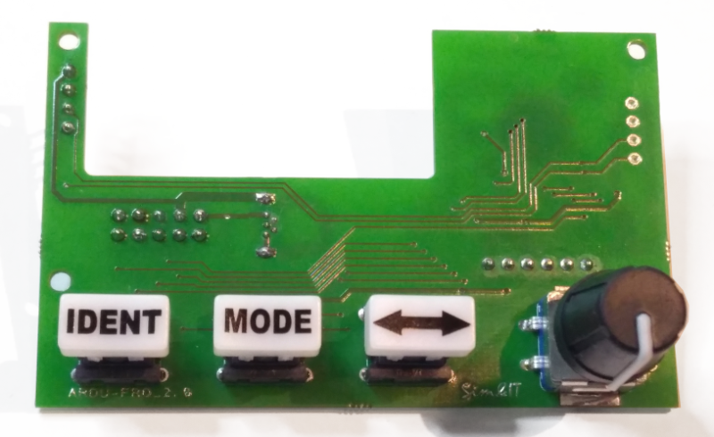 |  |  |
This PCB variant is only used with the version for the programmed module because of the SMD assembly and initial programming of the IC.
ALternative Display
Red LC displays and OLED displays of similar design are also available. The I²C-to-parallel converter must be procured and mounted separately in each case. With the red LC displays, however, the viewing angle is not very large and the contrast decreases. The OLEDs are very clearly viewable, but the control is somewhat different, especially the initialisation. The OLED displays are considerably more expensive. The OLED displays are considerably more expensive.


M2.5 stud bolts were inserted into an acrylic plate and the circuit board is mounted to them.
Front panel
A cover made of photo paper was glued onto the acrylic plate.
Cover
NAVCOM Panel
Based on the avionics panel of variant 2, this board was extended by a second display, three buttons and an encoder. This makes it possible to set or display the COM frequencies and the NAV functions with the NAVCOM panel. The ATmega328 is integrated on the PCB.
The functions correspond to the NAV and COM individual displays, but only one network connection is necessary. The modes are descibed below.
Two function versions are possible, COM1 and NAV1 or COM2 and NAV2. The function can be reprogrammed during switch-on/boot-up by holding down one of the two SWAP buttons <->.

- Printed circuit board ARDU-NAVCOM 5cm x 16cm
- with integrated and programmed ATmega328 (boot loader and sketch)
- two rotary encoders
- six push buttons
- two LCD modules 2×16 characters, I²C control, the I²C addresses must be configured differently
- Ethernet module WizNET W5500 to connector J3

- J3 is also used for programming the boot loader on the ATmega328.
- Power (+5V) is supplied via a mini USB socket J4 or via the FTDI connector.
- A USB-serial converter for programming via the Arduino IDE can be connected to the FTDI connector.
Printed Circuit Board
NAVCOMM Version Dual Encoder

For the version with dual encoders, the inputs of the Arduino are only sufficient for connecting 4 buttons, which are then the two swap buttons, the mode button on the NAV and the push button on the rotary encoder. For this version I also used LC displays with a red background. These displays have a very limited lateral viewing area. The contrast decreases significantly. But it looks more realistic. Everything was mounted on a front panel onto which a printed photo paper was then glued.
Multi-Function Panel (MFP)
 The Multi-Function Panel combines the six functions that are possible with the avionics module described above. Use the buttons on the side to switch between functions. The functions COM1, COM2, NAV1, NAV2, ADF and XPDR are available.
I tried to synchronize the functions with the flight simulator, but these commands are often not supported by the developer of the aircraft panel.
The modes are descibed below.
The principle is the same as in the avionics modules described above. There is a socket for the Arduino Pro Mini on the carrier plate. LCD and Ethernet module are connected to pin headers.
Only the Ethernet module WIZnet W5500 is supported..
- PCB ARDU-MFP 5cm x 12cm
- Arduino Pro Mini (5V, 16 MHz) in socket U1, the Pro Mini has two separate Pins for A4/A5 = I²C-SDA/SCL
- LCD module 2×16 characters, I²C-SDA/SCL at A4/A5, direct at Arduino module, power supply at connector J2
- Ethernet module WizNET W5500 at connector J3
- Rotary encoder at A2/A3, alternativ dual encoder at A2/A3 and A0/A1
- Push button and buttuns are in a 3×4 matrix at D2..D4/D6..D9
Power (+5V) is supplied via a mini USB socket J4 or the connector at the Arduino.
Schematic
Assembly
Shared PCB at Aisler
BOM
Example with front panel

A black acrylic plate was laser-machined for the structure shown. Six 2.5 mm stud bolts were inserted into the plate to which the circuit boards are mounted.
Front panel
A cover made of photo paper is glued onto the acrylic plate.
Cover
As with the avionics modules, the ATmega328 was integrated on the circuit board. This variant is used for the version for the programmed module.
ESP8266 Hardware WIFI (Test version)
This variant has the same design, but is not driven by an Arduino Pro Mini, but by a board with the processor ESP8266. This contains a WIFI module with complete IP stack. Programming continues via the Arduino IDE, the ESP hardware can be added to the IDE. See here.
The WeMos D1 mini module contains a USB to serial converter and can thus be connected directly to the PC and programmed from the IDE.
The program could be almost completely transfered with fix programmed SSID / password only by changing the libraries and adjusting the ports.
Major changes came with the support of WPS. With this feature, the router (which must support WPS) and the device negotiate the connection data within a short period of time after pressing the WPS button on the router and then the WPS button on the device.
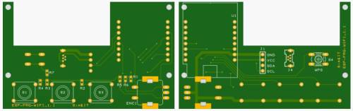
The circuit board contains a socket to connect the WeMos D1 mini module
- PCB Ardu-FRQ-WIFI 5cm x 8cm
- LCD-Modul 2×16 Zeichen, I²C-SDA/SCL at D1/D2, supply and I²C over 4 pin connector J1
- Rotary encoder at D0/D3, push button at D4
- three buttons at D5 .. D7
- WPS button at D8
Power (+5V) is supplied via a mini USB socket J4 or via the USB socket of the WeMos module.

Printed Circuit Board
Software
Arduino Sketch
The avionics panel with the Arduino sketch is a front end to the SimConnect client or X-Plane plug-in.
The panel connects to the communication software on the PC, events are transmitted to it and the variable values supplied are displayed.
The Ethernet module is connected to the network and must get a network address via DHCP. The WIFI variant must exchange the connection data once via WPS with the router and then also receives a network address from the DHCP server. For the data connection the UDP protocol is used. It should be noted here that a unique MAC address and a unique port are always neccessary. Both are defined in the sketch.
Active and standby frequencies are supported in the COM panel, with the buttons you can activate the transmit mode and the receive-both mode.
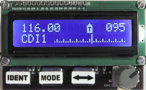
The NAV panel is programmed more complex. In addition to the active and standby frequencies, a simple scale representation of the CDI is also possible. This feature is possible with the use of custom characters on the LCD panel. The display functions are implemented by the SimConnect client or the X-Plane plugin.
When starting or resetting the controller, the module function can be changed by pressing the three keys during start/reset. This change is stored in the EEPROM memory of the controller so that this setting is retained until it is changed again.
Key variants for changing the function:
right key            COM1
middle key           NAV1
right + middle key   COM2
left key             NAV2
left + right key     ADF
left + middle key    XPDR
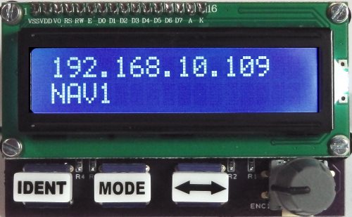
The started software displays the function and briefly the assigned network address and then waits for the connection to be established by the communication software. If connected, the Arduino software knows where to send the data.
- Displays the assigned IP address for ca. 3s
- Then wait for the connection to be established by a communication program of a flight simulator (FSX/P3D-SimConnect-Client, X-Plane-Plugin)
- Displays the connection status
 | 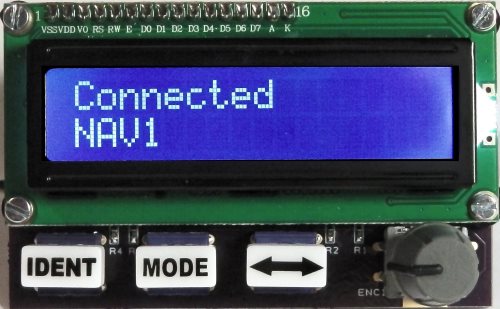 |
If the connection is established key and encoder events can be sent and data can displayed by the communication software in appropriate format.
Communication Software
The communication software establishes the connection between the flight simulator and the avionics panel. If a PC has found more than one network card, it must be defined via the client's/plugin's configuration file. At startup, the found network adapters are listed with their ID.
Via the network adapter, a request is sent to the broadcast address of the network segment and the UDP port assigned to the respective panel function (this must match the sketch) to search for the Avionics Controller. The Avionics Controller receives this request and thus knows the IP address of the sending communication software. The confirmation is then sent to this IP address, whereby the controller IP address is transmitted to the communication software. The connection is now established. The controller now knows the IP address of the Flight Simulator and the Flight Simulator knows the IP address of the controller.
Now events of the avionics panel can be sent via UDP to the client/plugin, which then converts them into flight simulator events or sets display variants. The updated variables are converted into display strings and sent back to the avionics panel in defined form and displayed on the LCD panel
Cyclically it is queried whether the panel is still in the system. If, within a certain time, no response is received to this request, then the client/plugin goes back into the call setup phase and sends search requests on the broadcast address.
SimConnect-Client
 The SimConnect client (FSX, FS2020, P3D) is a stand-alone program and can be started directly from a folder, e.g. the installation folder. The configuration file
 Arduino-Panel.cfg can be created in this folder or in a subfolder of the AppData area.
.\AppData\Roaming\Sim&IT\SimConnect\Avionics-Panel.cfg
→ More information about the Arduino SimConnect clients and their configuration can be found here.
Client Setup FSX
Client Setup FS2020
X-Plane-Plugin
 The X-Plane plugin corresponds to a DLL. These are stored in the subfolder
 .\ressources\plugins. The found plugin can be displayed in the started flight simulator via the menu. The info area displays either the connection to the Arduino panel or the selection of network adapters if more than one adapter was found. This must be defined in the configuration file.
.\AppData\Roaming\Sim&IT\X-Plane-Plugins\Avionics-Panel.cfg
→ More information about the Arduino X-Plane plug-ins and their configuration can be found here.
Plugin Setup
Functions
The function of the panels can be changed by pressing keys like written in the section Artuino Sketch when the operating voltage is switched on.
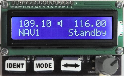
The COM-Panel shows the Active/Standby frequencies. The following functions are possible:
- ACTIVE/STANDBY mode ⇒ displays Active/Standby frequencies
- Rotary encoder changes the Standby frquency, Push Button changes betweend whole ans fractured values
TRANSactivates the panel as transmitter, indicated byT←→swaps between standby and active frequencyMODEswitches the Both-Receive mode on/off, indicated by a speaker symbol
The functions of the NAV-Panel are based at some functions of KX155A/KX165A.
the following states are possible:
 |  |  |  |  |  |
 |
- ACTIVE/STANDBY mode ⇒ displays Active/Standby frequencies
- Rotary encoder changes the standby frequency, push button changes between whole and fractured values
IDENTactivates the respective NAV Sound, indicated by a speaker symbol←→swaps between standby and active frequencyMODEswitches to the ACTIVE/CDI mode
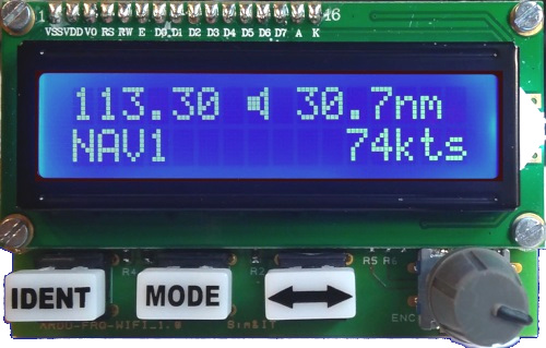
- ACTIVE/CDI mode ⇒ displays the active frequency, the Course Deviation Indicators (CDI) and the OBS Course
- Rotary encoder changes the active frequency, push button changes between whole and fractured values
IDENTactivates the respective NAV Sound, indicated by a speaker symbol←→swaps between the hidden standby and active frequency- Scale with +/- 16 dashes (15 dashes correspond to the 5 dots of the round instrument)
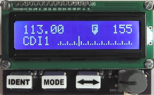
- at a VOR the
TOorFROMis shown in the middle of the scale- at
TOa ca. 2s push at the axis of the rotary encoder may acquire the actual Bearing-TO course - a double click at the axis of the rotary encoder changes to the OBS mode, indicated with
>- in OBS mode an additional click switches between the Fast Mode (+/-5°) on/off
- after 2s without activity changes back to the frequency adjust mode
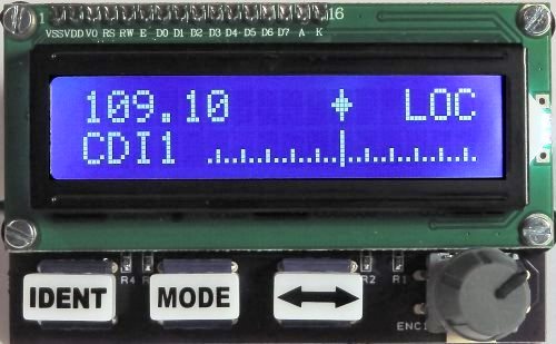
- at a Localizer a diamond is shown in the middle of the scale and
LOCinstead of the OBS course- a double click at the axis of the rotary encoder changes to the OBS adjust mode but this has no effect to the CDI, it is informative
- If no signal is detected, there is a line in the middle of the scale, the needle is also in the middle
MODEswitches to the ACTIVE/BEARING mode
- ACTIVE/BEARING TO mode ⇒ displays the active frequency and the course to the station (Bearing TO)
- invalid signal is indicated by three hyphen
- Rotary encoder changes the active frequency, push button changes between whole and fractured values
IDENTactivates the respective NAV Sound, indicated by a speaker symbol←→swaps between the hidden standby and active frequencyMODEswitches to the ACTIVE/RADIAL mode
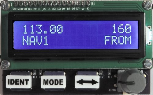
- ACTIVE/RADIAL FROM mode ⇒ displays the active frequency and the course away from the station (Radial FROM)
- invalid signal is indicated by three hyphen
- Rotary encoder changes the active frequency, push button changes between whole and fractured values
IDENTactivates the respective NAV Sound, indicated by a speaker symbol←→swaps between the hidden standby and active frequencyMODEswitches to the ACTIVE/DME mode
- ACTIVE/DME mode ⇒ displays the active frequency and the DME information
- invalid information is indicated by minus
- Rotary encoder without function, push button selects/deselects the DME, indicated by
sel IDENTactivates the respective DME Sound (only in selected mode), indicated by a speaker symbol←→swaps between the hidden standby and active frequencyMODEswitches to the ACTIVE/STANDBY mode
The ADF-Panel displays the following modes:
- ACTIVE/STANDBY mode ⇒ displays Active/Standby frequencies
- Rotary encoder changes the Standby frequency, push button changes between whole and fractured values
IDENTactivates the ADF1 Sound, indicated by a speaker symbol←→swaps between standby and active frequencyMODEswitches to the ACTIVE/RAD mode
- ACTIVE/RAD mode ⇒ displays the active frequency, the ADF needle and ADF-HDG
- Rotary encoder changes the active frequency, push button changes the digit that is adjusted
IDENTactivates the ADF1 Sound, indicated by a speaker symbol←→swaps between the hidden standby and active frequency- If no signal is detected, there is a line in the middle of the scale, the needle is also in the middle
- an active signal is indicated by a diamond sign
- the scale indicates +/- 50°, a larger deviation is indicated with
<or>at the end of the scale - a double click at the axis of the rotary encoder changes to the ADF-HDG mode, indicated with a
>- In HDG mode an additional click switches between the Fast Mode (+/-5°) on/off
- after 2s without activity changes back to the frequency adjust mode
MODEswitches to ACTIVE/ET mode
- ACTIVE/ET mode ⇒ displays the active frequency and an Elapsed Timers
- Rotary encoder changes the active frequency, push button changes the digit that is adjusted
IDENTstarts/stops/sets the Timer←→swaps between the hidden standby and active frequencyMODEswitches to ACTIVE/STANDBY mode
The Transponder-Panel XPDR displays the Flight Level and the Transponder Code.
- Rotary encoder changes the transponder code, push button changes between the digits, after approx. 5s is set back to left digit
- a ca. 2s push at the axis of the rotary encoder sets the code that is defined in the configuration file (default 1200)
- only in X-Plane and MSFS2020:
IDENTactivates the Transponder IDENT←→switches between ON and ALTMODEswitches between OFF and Standby
Links
Installation instructions
Development of the Flightsim panels in german
Encoder Controller (english)
Audio-Panel
Autopilot in german
Cockpit-Panel-PC in german